RoadScan
RoadScan
Complete GPR System for Road Inspection
The RoadScan™ 30 system provides users with an effective tool for quickly determining pavement layers at high speeds. RoadScan is able to collect data densities not obtainable using other labor-intensive methods commonly used for pavement testing.
-
Max Depth
91 cm (3 ft)
-
Antenna Options/ Antenna Frequency
2 GHz, 1 GHz
-
Weight
49.8 kg (110 lbs)
-
Storage Capacity
900 GB
-
Optional Software
-
Accessories
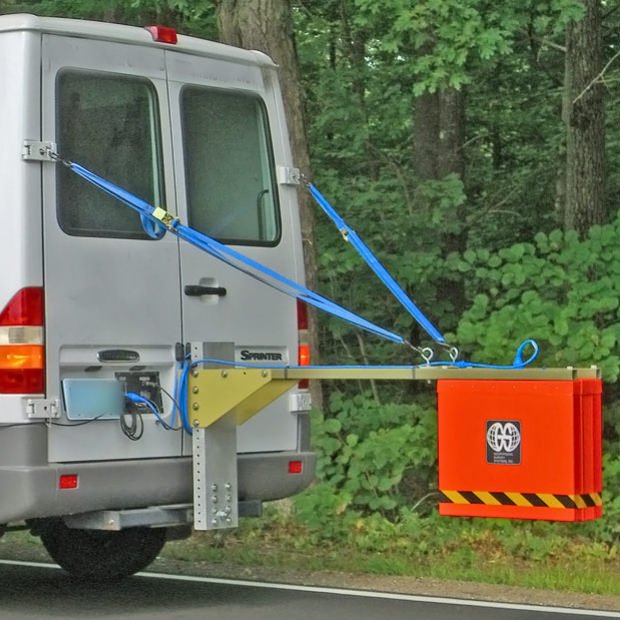
Antenna vehicle front mount, Antenna vehicle trailer mount
Typical Uses
The RoadScan 30 is typically used to:
- NDT road evaluation
- Measure pavement thickness
- Evaluate base and sub-base conditions
- Measure asphalt prior to milling operations
- Determine areas to core
System Includes
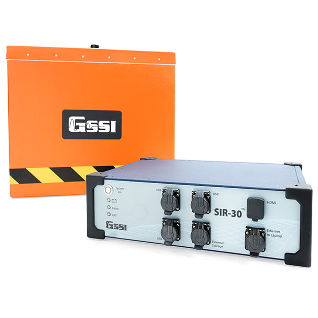
- SIR 30 Control Unit
- 1 or 2 GHz Horn antenna
- Wheel-mounted distance measuring instrument (DMI)
- 7 m control cable
- SIR 30 power supply
- SIR 30 transit case
- 2-year warranty
Upcoming Training Events

-

Non-destructive Pavement Testing
The RoadScan can quickly collect pavement layer thickness data. The system acquires data at highway speeds, which eliminates the need for lane closures and provides a safer working environment.
-

Deliver Pavement Evaluation Results
Data can be easily exported as ASCII output files for simple data transfer to other software programs. Or migrate data results as Google Earth™. kml file for enhanced visualization.
Data Examples
Specifications
| System | SIR 30 |
| Antenna Support | Compatible with all GSSI analog antennas |
| Number of Channels | Records data from 1 to 4 hardware channels simultaneously; two 4 channel systems can be connected to form an 8 channel system |
| Data Storage | Internal memory: 900 GB, GPS data logged internally |
| Display Modes | Linescan and O-scope. In Linescan display, 256 color bins are used to represent the amplitude and polarity of the signal |
| Operational Modes | External laptop, standalone with external monitor and keyboard or remote command set |
| Data Acquisition | |
| Data Format | RADAN® (.dzt) |
| Scan Rate Interval | User-Selectable |
| Output Data Resolution | 32-bit |
| 1-4 Channels @ 100 KHz PRF | Samples | Max Rate (scans/Sec) |
| 256 | 326 / 512 | 178 / 1024 | 93 / 2048 | 48 / 4096 | 24 / 8192 | 12 / 16,384 | 8 | |
| 1-4 Channels @ 800 KHz PRF | Samples | Max Rate (scans/Sec) |
| 256 | 1449 / 512 | 990 / 1024 | 606 / 2048 | 341 / 4096 | 182 / 8192 | 94 / 16,384 | 48 | |
| Samples per Scan | 256, 512, 1024, 2048, 4096, 8192, 16,384 |
| Time Range | 0-20,000 nanoseconds full scale, user-selectable Gain: Manual adjustment from -42 to +126 dB. Number of segments in gain curve is user-selectable from 1 to 8. |
| Standard Real-time Filters | Linescan and O-scope. Infinite Impulse Response (IIR) - Low and High Pass, vertical and horizontal Finite Impulse Response (FIR) - Low and High Pass, vertical and horizontal |
| Advanced Real-time Filters | Migration, Surface Position Tracking, Signal Floor Tracking, Adaptive Background Removal |
| External Marker | Three different inputs/codes: Antenna, Front panel, Accessory connector |
| Automatic System Setups | Linescan and O-scope. Storage of an unlimited number of system setup files for different survey conditions and/or antenna deployment configurations |
| Languages | English and Chinese |
| Operating | |
| Operating Temperature | -10°C to 50°C external (14°F to 122°F) |
| Power | 260W max at 95-250VAC 50/60Hz with the AC supply or 30A max continuous at +10VDC to +28VDC |
| Transmit Rate | Up to 800 KHz (International), US/Canada and CE rates depend on antenna model |
| Input/Output | |
| Available Ports | Antenna inputs (2 or 4), Survey wheel, Marker, DC power input, Serial RS232 (GPS port), Sync connector, Accessory connector, HDMI video, Ethernet to PC, 4 USB ports |
| Mechanical | |
| Dimensions | 17.7 x 13 x 5.1 in (45 x 33 x 13 cm) |
| Weight | 18.5 lbs (8.4 kg) |
| Relative Humidity | <95% non-condensing |
| Storage Temperature | -40°C to 60°C |
Resources
Accessories
